
Notice:
This post is older than 5 years – the content might be outdated.
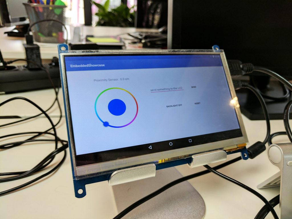
Android updates are rare, especially for development boards. We were running such a deprecated board once built to demonstrate our knowledge in embedded Android. Since we didn’t want to rely on a deprecated showcase, we decided to build a completely new setup bringing together the old show case, an ordinary Android extended with a line LCD display, usable via an SDK-Add-on, and an integrated sensor, previously described here.
We wanted to base the new showcase on a modern development board for which at least sources for Android 5 were available, a touch display, the Grove-LCD display and finally the sensor integration.
Simple enough, right? We’d just have to add the old code to the new Android version – Nope! That would have been too easy. Let’s have a look at everything that went wrong.
At first, a new development board was needed. We chose the Wandboard Quad because Android 5 was available with 6 already announced. Indeed, Android 6 was released when we finally started development (let’s hope they keep up the support!).
Part 1 – Adding a touch display via HDMI? Just give me 5 minutes …
So we had a board and wanted to attach a touch display. Due to some issues and limitations of the Wandboard’s CPU we were limited to an HDMI connection and for simplicity the display should have a USB touch controller, both of which limited our choice. On the first try, the picture was distorted and we were not able to adjust the touch driver, so some UI elements were not touchable. The next try seemed to work much better—sharper picture, much better touch controller—while testing it with a Raspberry Pi. When we switched to the Wandboard we got a picture only while the boot loader was active, afterwards things went south.
Due to the display’s advantages, we absolutely wanted to run this one, so a long frustrating time of debugging started.
Normally, Linux gets its parameters, amongst them the screen settings, as boot parameters. So we tried to modify them, but they were ignored. Analysing the dmesg logs brought us on the right track: the frame buffer, the Linux graphics memory. So we looked up the display settings with
|
1 |
cat /sys/class/graphics/fb0/modes |
which returned only one resolution:
|
1 |
V:640x480p-60 |
This didn’t match our display’s resolution of 1024×600 pixels. Hence, we needed to define a new one. The dmesg log helped us again with this string:
|
1 |
mxc_sdc_fb |
. Grepping for this string in the kernel files brought us to the right directory and the file kernel_imx/drivers/video/mxc/mxc_hdmi.c. There, neatly at the file’s beginning, we found a definition for the one existing frame buffer mode.
Now we needed just one more thing to add a suitable mode for our display—the matching parameters. A frame buffer mode definition consists of a pile of weird looking numbers. How do we find the right ones? This brought us back to the boot loader. As you may remember I wrote that during u-boot a correct picture was display. We looked up the u-boot sources and found what we needed. With this knowledge, it was just 5 lines to change in the file
|
1 |
kernel_imx6/drivers/video/mxc/mxc_hdmi.c |
for a cool working display:
|
1 2 3 4 5 6 7 |
static const struct fb_videomode waveshare_mode = { NULL, 60, 1024, 600, 13806, 150, 40, 21, 7, 60, 10, 0, FB_VMODE_NONINTERLACED, 0 }; |
And in the same file in the function mxc_hdmi_edid_rebuild_modelist (struct mxc_hdmi *hdmi):
|
1 |
fb_add_videomode(&waveshare_mode, &hdmi->fbi->modelist); |
Touch support worked out of the box and no calibration was needed, so after rebuilding and flashing we were could continue our adventure with a working touchscreen.
Read on
In the next part we will port the kernel drivers to the new Android version before we have a look at the HAL and the Android framework. In the meantime, have a look at our Smart Devices division and learn how you can join us as a software developer.


