


TL;DR:
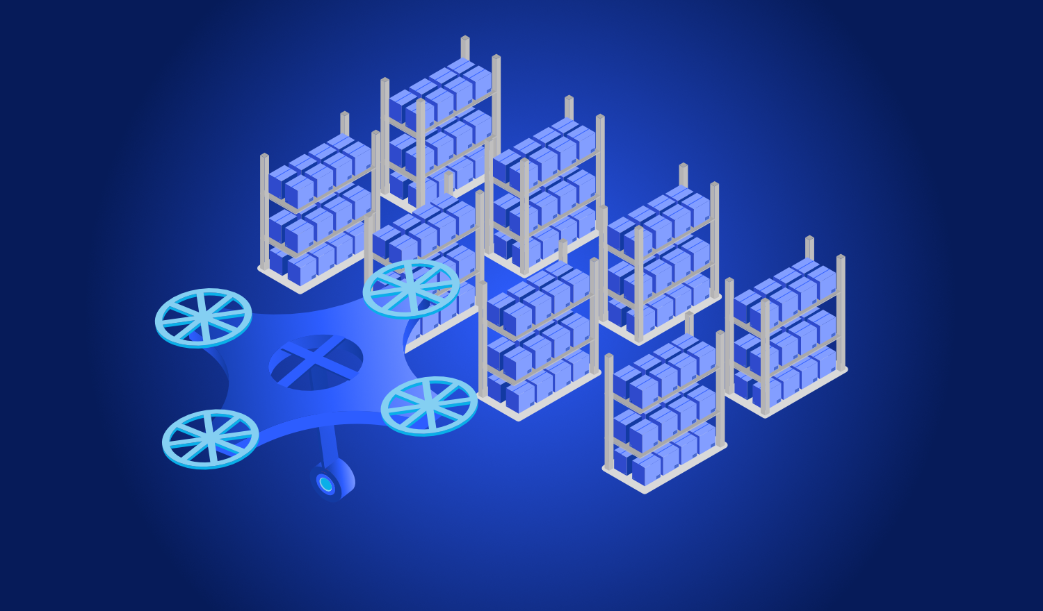
This project involves a simulation in which a hexacopter navigates through a virtual warehouse without the use of GPS, mapping the environment as a point cloud via LiDAR. The system runs on a standard laptop using open-source software and is designed to be transferable to a real-world drone.
This article is a (partly) automated translation of the German original.
A drone intended to fly autonomously in an indoor space without GPS reception must determine its own location. A drone simulation using PX4 addresses precisely this challenge: a hexacopter navigates through a virtual warehouse, mapping the environment using LiDAR—all without the need for any physical hardware to take flight.
Outdoors, satellite signals handle localization. Indoors, however, these signals are unavailable, forcing the drone to orient itself solely based on its surroundings. Developing such systems using actual hardware is both costly and risky, as every crash incurs expenses and consumes time. In a simulation, by contrast, the same experiment can be repeated as often as necessary under identical conditions—and the entire system can run on a standard laptop.
Ein Hexacopter navigiert per LiDAR-SLAM durch die simulierte Lagerhalle „Jetty World" (Gazebo Harmonic).
The Simulation Environment
The environment consists of three programs working in tandem:
PX4 serves as the autopilot. It keeps the drone stable in the air and controls its six motors. Crucially, it runs the exact same software that will later be used on a real drone; the system cannot distinguish whether its sensor data originates from the simulation or from actual hardware. This allows for a seamless transition of the system onto a physical drone.
Gazebo represents the simulated world. It calculates the physics—determining how the drone responds to thrust and gravity—and generates sensor data from the LiDAR, orientation sensors, and cameras. This data is intentionally imperfect: Gazebo introduces realistic noise into the measurements, ensuring that the test yields meaningful results rather than relying on idealized, unrealistic data.
ROS 2 acts as the connective tissue. It executes custom programs and ensures that sensor data is delivered exactly where it is needed.
-
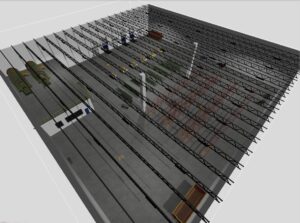
The “Jetty World” warehouse in Gazebo. Walls, shelves, and containers provide the LiDAR with enough structure for mapping.
How the drone is constructed
The simulated drone is a hexacopter—a multicopter with six rotors. It weighs two kilograms and is modeled after an actual drone from Offenburg University of Applied Sciences.
The six rotors are arranged in a star pattern around the center. Three rotate clockwise, while the other three rotate in the opposite direction. This is no coincidence: every rotating rotor generates a counter-torque, and only when these torques cancel each other out can the drone avoid spinning uncontrollably on its own axis. The PX4 system knows the position and direction of rotation for each motor and distributes the required thrust across all six accordingly.
Two sensors are essential for mapping. A LiDAR system scans the surroundings using 16 stacked laser planes, generating a point cloud ten times per second. An inertial measurement unit (IMU) records acceleration and rotational rates 250 times per second. There is also an onboard camera, though it is not used for the mapping process.
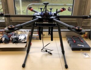
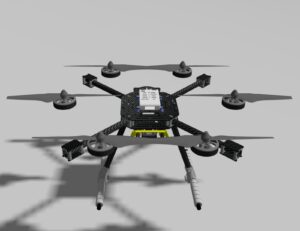
The actual reference drone from Offenburg University of Applied Sciences (left) and the replicated simulation model (right). The main difference is the LiDAR sensor, which is already mounted on the simulation model.
Point Clouds and the Map
A point cloud is a collection of measured points in space. With each rotation, the LiDAR sensor emits laser beams in all directions, measuring the distance to the nearest surface. By combining 16 planes with 360 measurements each, the system generates approximately 5,760 points per scan, which outline walls, shelves, and containers.
The drone uses these scans to construct its map. This process is known as SLAM (Simultaneous Localization and Mapping), as the drone localizes itself while simultaneously mapping its environment. Relying solely on an inertial measurement unit (IMU) or position sensor would cause the drone’s estimated position to drift over time, as small measurement errors accumulate. To counter this, the drone compares each new LiDAR scan against the data already collected, continuously correcting its position. In this way, a coherent point-cloud map of the hall is built piece by piece as the drone flies.
Specifically, the system employs RKO-LIO—an open-source method developed by the University of Bonn’s Photogrammetry & Robotics Lab. It functions effectively across a wide variety of vehicles using a single set of parameters, requiring no complex fine-tuning. This aligns with the ultimate goal: to deploy the system on actual hardware later with minimal effort.
-
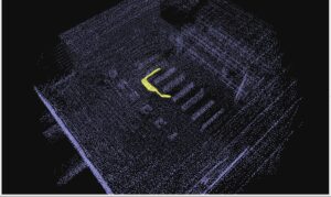
Die Punktwolkenkarte, die während des Flugs entsteht. Die Drohne ist als Zylinder mit Spitze in Blickrichtung dargestellt.
What the drone simulation with PX4 achieves
During the test, the entire system chain functioned as intended. The drone could be steered in any direction, all sensor data was received reliably, and the map was generated accurately in sync with the drone’s movement. This demonstrates that getting started with autonomous drones does not require expensive hardware. A laptop and a few open-source software components are sufficient to fly a drone through a hall while observing the mapping process in real time.
Code and Tools
The complete project code is available as open source on GitHub: khttps://github.com/TheKnightOfLuck/drohne-px4
Open-source components used: PX4 (https://px4.io), Gazebo (https://gazebosim.org), ROS 2 (https://docs.ros.org), and RKO-LIO from the Photogrammetry & Robotics Lab at the University of Bonn (https://github.com/PRBonn/rko_lio).
This blog post was created as part of an academic project.
Offenburg University of Applied Sciences
Thesis title: “Evaluation and Implementation of Flight Control Software for Fully Autonomous Drones”
Timeframe: October 1, 2025 – June 1, 2026
